- Pcb Design Ipad Pro
- Pcb Design Ipad Screen
- Pcb Design Tutorial
- Pcb Artist
- Pcb Design Services
- Pcb Design Ipc
Online PCB Design Tool. 1,575,255 Engineers Chose EasyEDA for 5,297,243 Designs. Download Free trial. More Than 1 Million Free Libraries. More than 1 million real-time updated components have been created, letting you focus on the design, and you can create or import your own common libraries.
- PCB Design Tutorial by David L. Jones Page 3 of 25 3 Introduction You've designed your circuit, perhaps even bread boarded a working prototype, and now it's time to turn it into a nice Printed Circuit Board (PCB) design. For some designers, the PCB design will be a natural and easy extension of the design.
- Have your ever designed a printed circuit board on your tablet? This time you can make your own PCB design on your iPad! It's FREE, easy to use, easy to learn. Soldering iron stockPCB Droid is a.
When designing PCB pads in PCB board design, it is necessary to design strictly accordance with relevant requirements. Because in the SMT processing, the design of the PCB pad is very important, the pad design will directly affect the solderability, stability and thermal energy transfer of the component, ralated to the SMT quality. So what is PCB pad design standard?
First, the design criteria of the shape and size of the PCB pad:
- Refer to the PCB standard package library.
- There is a minimum of 0.25mm on one side of the pad, and the maximum diameter of the whole pad is not more than 3 times the aperture of the element.
- Try to ensure that the distance between the edges of the two pads is greater than 0.4mm.
- Pads with a hole diameter of more than 1.2 mm or a pad diameter of more than 3.0 mm should be designed as diamond or plum-shaped pads.
- In the case of dense wiring, it is recommended to use oval and oblong lands. The diameter or minimum width of the single-panel pad is 1.6mm; the weak-circuit pad of the double-panel requires only 0.5mm of the hole diameter, and the excessively large pad may cause unnecessary soldering.
Second, the PCB pad via size standard:
The inner hole of the pad is generally not less than 0.6mm, because the hole smaller than 0.6mm is difficult to process when punching, and the metal pin diameter value plus 0.2mm is usually used as the hole diameter of the pad, such as when the metal pin diameter is 0.5 mm of the resistor, the hole diameter of the pad corresponds to 0.7 mm, and the diameter of the pad depends on the diameter of the inner hole.
Third, the reliability of the PCB pad design points:
Pcb Design Ipad Pro
- Symmetry: in order to ensure the balance of the surface tension of the molten solder, the pads at both ends must be symmetrical.
- Pad pitch: if the pitch of the pad is too large or too small, it will cause soldering defects, so we need to make sure that the component terminals or pins are properly spaced from the pads.
- The remaining dimensions of the pad: the remaining dimensions of the component terminals or pins after bonding to the pads must ensure that the solder joints can form a meniscus.
- The pad width should be substantially the same as the width of the component terminals or pins.
The correct PCB pad design, if there is a small amount of crook during the processing of the SMT, it can be corrected by the surface tension of the molten solder during reflow. If the PCB pad design is not correct, even if the placement position is very accurate, after the reflow, it is easy to have component position offset, suspension bridge and other soldering defects. Therefore, when designing the PCB, the PCB pad design needs pay a lot of attention.
Kindly please feel free to contact Kola@sdy-pcb.com or our engineer if you want more information on Pad design in PCB design.
- Preview:Printed Circuit Board Electrical Testing
- Next:Slowing Growth of PCB Sales in North America
The field of electronics have witnessed a lot of advances over time, and this has been key to the technological advances witnessed over time. One of the important elements that have made it possible to have relatively small gadgets is the tremendous improvement and refinement of PCB layout software applications. This makes it a division of electronics that is important to look at especially from the advances that it presents to the users.
Related:
Open Source PCB
Open Source PCB layout software, free download offers an exciting way for designing various PCB layouts and can be run on 1 to 16 copper layouts making it considerably powerful. At the same time, the software is able to use English as well as metrics making it versatile.
PCB Design Layout Software
PCB Design Layout Software is a great PCB layout software free. download full version that has capabilities that can hardly be matched by any other software in the market. The software features a comprehensive library and lots of components that make it very easy to develop any PCB layout.

DesignSpark PCB


DesignSpark PCB is easy to learn and use application for designing and implementing different PCB layout. It is arguably one of the most accessible software in the category and presents unmatched features. With this software, the user has access to over 80,000 online parts and thus making development quite smooth.
Other Platforms
Primarily, since most of the software available for this role require installation into the system, there is a need to consider the platform they ride on. In the following segment of the review, we will do this to highlight a software for each of the popular platform.
PCB Layout for Mac
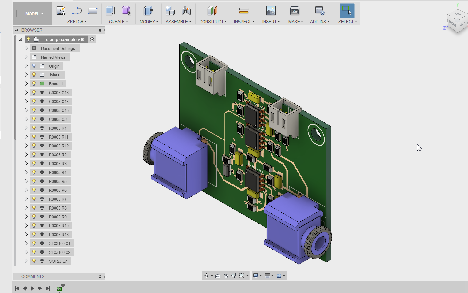
PCB Layout is a PCB layout design software available for the users on the Mac platform to assist in designing of PCB layouts. Essentially, the software is a cross-platform and open source, and this makes it quite resourceful. The software is well detailed even offering a 3D view to make the design process effective.
Pcb Design Ipad Screen
PCB Droid for Android
Pcb Design Tutorial
PCB Droid is an exciting Android App to assist when it comes to developing PCB layouts. The App is quite detailed and allows the user to export the files to GERBER for professional application. At the same time, you can save your progress on the cloud meaning you will never lose the progress.
Express PCB CAD Software for Windows
ExpressPCB CAD Software is a free application that can be accessed by the users on the Windows platform. The software supports both PCB as well as schemas and thus it is considerably powerful. Also, the software is compatible with all the versions of Windows OS starting from XP to Win 10.
Pcb Artist
Most Popular Software for 2016 – Dip Trace PCB Layout
Pcb Design Services

DipTrace is a leading PCB Layout software based on the features as well as on the number of users. The software features a schematic, PCB layout, and a 3D preview to present the developer with all the necessary information about the system. The company also offer high-level support to users. You can also see Electrical Plan Software
What is PCB layout Software?
Pcb Design Ipc
A PCB layout software is a piece of a computer program that can be used by electronics engineers as well as technicians to develop the layout of various PCBs. PCB is an acronym for the print circuit board, and they are responsible for the considerable smaller electronic gadgets. With the software in this category, the users are able to simulate various configurations and layouts of PCBs and thus concentrate on developing the most ideal. You can also see Electrical CAD Software
Typically, PCB layout software applications also offer other capabilities especially schematic capture and 3D previewing. This is done in the spirit of enhancing the experience of the developers.The PCB layout software list is quite extensive and this being the case, it is not possible to sample all the software available for this purpose. The above-sampled software are some of the best available software, and thus they happen to be the most recommended.
Related Posts
